
Set up
Check your parts
Check you have all the major parts.
4x 4080 700mm
2x 4080 600mm
2x 4080 484mm
2x 4080 187mm
2x 4040 500mm
1x 4040 484mm
2x 4040 350mm
15x L bracket with caps sets
4x double brackets
4x universal brackets
1x Allen key set
1x spanner
1x spirit level
Notes
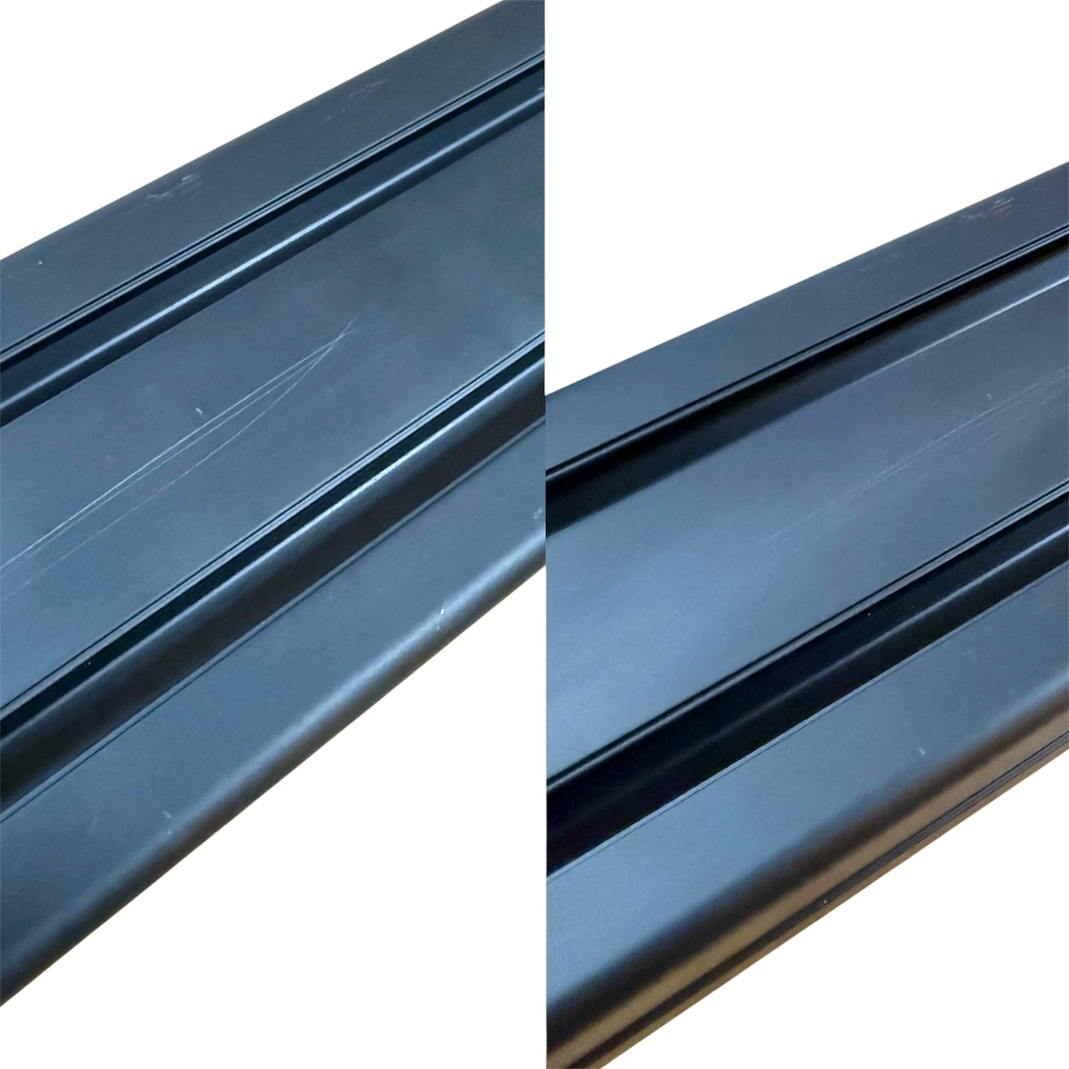
Before starting
The profiles are anodised aluminium. They can be scratched without careful assembly; however, if there does appear to be a scratch, most of the time they can be rubbed off with your fingers.

Notes
Please reference our fastener guide to check the names and sizes of your fasteners to ensure you are using the correct ones for each step.
Notes
Use the 3D model, images, and drawings on the product page to check how the rig should look.
The final image on the product page is a 3D model that can be viewed on the majority of phones, tablets, and computers.

Notes
The L brackets with caps may need the tabs broken off for some accessory mounting.
These can be easily snapped off with leverage from a flat-head screwdriver.

Notes
Be careful with the edges of the aluminium profile as they are sharp and can damage floors with the weight of the seat.

The Build
The best position for lengthwise connectors (orange dots).

The Build
Parts:
6x lengthwise connectors
24x M6 headless screws (grub screws)
Use the long slotted connectors to join the one 4080 600mm to a 4080 700mm.
Leave the outside two channels open. The other channels can be filled with these connectors. This is because we will need the outside empty at a later stage.
See the previous image for where to put them.
Lengthwise profile connectors are only used at this step, so make sure to use all the ones you have.

The build
Parts:
6x feet
6x M4 t-nut
6x M4x12mm bolts
Attach all the feet to the bottom of the 1300mm piece (built from 600mm + 700mm).

The build
Parts:
2x 4040 500mm pieces
8x bracket with cap
16x T head bolt
16x flange / collar nut
Next step is to connect the two long 1300mm pieces (these are the horizontal rails) with a 4040 500mm and capped brackets.

The build
Connect another 4040 500mm piece between the two horizontal rails with capped brackets. Tighten these finger-tight.

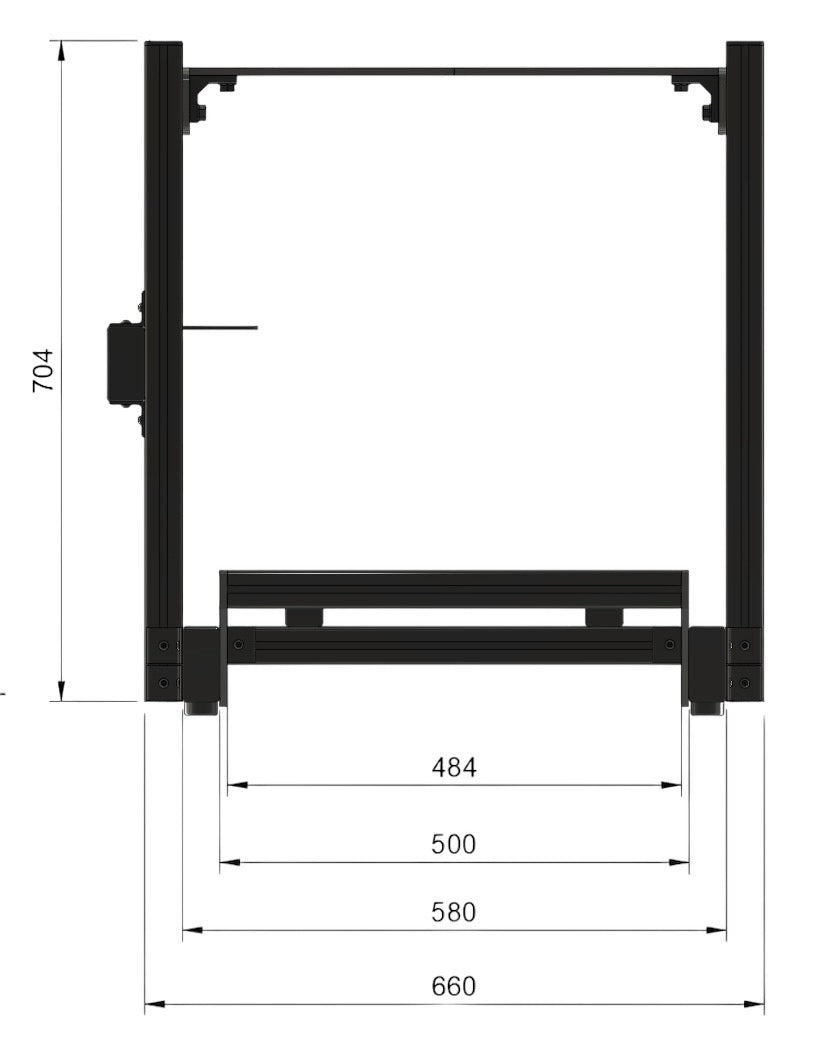
The build
Make sure to space these out approximately the length of the profiles for the bottom of the seat. They are the shortest, 350mm long.
Make sure the spacing is to the outer edges not the inner edge.

Uprights
Parts:
4x double brackets
16x M8x16mm button head screws
16x M8 sliding nut
Pre-assemble nuts and bolts into eight of the double L-shape brackets and slide them into position along the outside of the frame. Slide them along in a lifted position to prevent scratches on the outside.

The build
Position the gap between the brackets approximately 600mm from the open end of the frame without the cross connectors.
The Australian steel plate should be approximately 100mm closer to the driver (700mm form the open end).

The build
Leave them loose in the channel for now.

The build
Use the spirit level on top of the upright to make sure it’s vertical and not leaning over, then tighten the bolts to lock in the position.
Try to align the two uprights as close as possible by using the joint in the horizontal bars as a reference.
Uprights should not touch the ground. Try to make them flush with the bottom of the horizontal bars

The build
Slide / drop a 4080 700mm into each side. Keep everything loose to allow you to slide one bolt at a time into the bottom.

Steel top plate

Steel top plate
Parts:
1x Top plate steel
4x M8x20mm Button head bolts
4x M8 sliding nuts
4x M8 washers
Preassemble the sliding nuts and button head bolts onto the steel top plate. Use the orange markers / supports to prevent the top plate from dropping down when you slide it in the top.

Steel top plate
Fasten the plate into position so it doesn’t fall. Move the orange markers lower, then loosen the top plate and slide it down the uprights to rest on the orange markers.
The markers allow you to rest the steel top plate while you use your tools to connect it in place.
Slide it evenly (keep it level) down the uprights as it can scratch.

V2 Top plate

V2 top plate
Parts:
2x side brackets
4x M8x20mm countersunk head bolts
2x 4080 187mm
For V2 the plates are attached to the 2x short profiles instead of brackets.

V2 top plate
Parts:
8x M8 sliding nut
8x M8x20mm button head bolt
Slide / drop the top plate supports onto the inside of the uprights.

V2 top plate
Side assemblies attached to the uprights. Try to align these as much as possible.

V2 top plate
Parts:
8x M8x16mm countersunk head bolts
8x M8 sliding nuts
Top plate
Attach the top plate.
V2 top plate
If its slightly misaligned you can unscrew and adjust one of the arms.

The Seat
Assembling the seat
Skip this part if you don’t have a seat ready yet. Keep the 350mm pieces aside to attach to the bottom of the sliders, like in the picture.

The Seat
Start by attaching the shortest 4040, 350mm, to the sliders.

The Seat
You will need to manually move the slider to allow access to bolt them down.
Push down hard because the sliders can be hard to move.

The Seat
Attach the slider section to the bottom of the seat. This will require manually moving the slider again.

The Seat
Wedge the slider lever between the two sliders once they are securely attached to the seat. This will require a large amount of force to bend the bar so that it can be attached to the sliders.

Pedal plates
Parts:
6x M8x20 countersunk bolt
1x 4040 484mm piece
1x 4080 484mm piece
6x lever screws
6x M6 t-nut
6x M6 washer
May be required:
Universal brackets
Further T-nuts

Important
The handle and the screw are two separate parts. You can lift the handle to allow it to rotate freely without turning the screw. This means if the profiles get in the way just lift the handle and turn it back.
Please try this out before assembling the pedal area.

Pedal plates
Here is a video demonstrating how the handle can be moved independantly from the bolt.

Pedal plates
To build the pedal plate, start with planning how the pedals will connect. If it’s possible, connect the rear bolts of the pedals directly to the profile.
See some examples of different configurations below.
Always place the front bolts as close to the profiles as possible for maximum rigidity.

Pedal plates
The 484mm long pieces that go between the pedal plates will have a thread in the end, as highlighted in the photo.
The handbrake bar can also be put on the pedal area. You will only need two of the three pieces with threads to complete the pedal assembly.

Pedal plates
Note you can mix and match 484mm length between handbrake support and pedal supports.
If the pedals are too high, the whole assembly can be inverted as shown in this image.

Pedal plates
Add the lever bolts with washers to the pedal plate as shown.
Sometimes the profile gets in the way of turning the lever bolts. The head of the lever bolt can be pulled back to turn the bolt without turning the lever head.
Alternatively, the kit includes a standard bolt that can be used instead.

Pedal plates
Example of Fanatec pedals with pedal bar.

Pedal plates
Example of a standard pedal assembly for Fanatec, Moza, Simagic without pedals.

Pedal plates
Once the pedal plate is built, the safe assembly method is to disassemble and build the plate up directly, attaching the sides to the horizontal rails. Alternatively, the entire assembly can slide in from the back and along the slots.

Pedal plates
If the pedals are moving but the bolts are tight then the bolts have no turned in the slot as shown in the top slot the bolt is not engaged with anything.
To fix this unscrew your handle 4-8 turns then rescrew it. It should only turn a couple of time before its tight.

Pedal plates
Example of how to build a standard pedal plate with the Fanatec CSL / Moza CRP pedals.

Test fit
Now it's time to do a rough test fit.
Test fit
Parts:
4x bracket with cap
8x t head bolt
8x collar / flange nut
Attach the seat to the rig across the 500mm pieces you had spaced out previously.

Test fit
Bracket with caps attach the chair to the 500mm supports.

Test fit
Roughly check the distance from the seating position to where the wheel is where it’s expected to be.
This stage is not fine-tuning, just making sure it’s roughly in the right spot. Fine adjustment can be done by moving the pedals and top plate. You may need to move the upright to a better position depending on your body size and shape.

Test fit
Adjust the position of the components until an ergonomic seating position can be found.

Handbrake bar
Parts:
3x bracket with cap
6x t head bolt
6x collar / flange nut
Attach three brackets to the handbrake support bar. This is the last piece of 4080 profile and should be 484mm, the same length as the pedal profiles.

Handbrake bar
Attach this to the left of right upright.
Note: if you don’t want to use a handbrake, this part can be connected to the pedal assembly for extra support. Extra fasteners or brackets may be required.

Handbrake bar
Parts:
2x universal brackets
4x t head bolts
4x collar / flange nuts
Use the universal brackets to attach your shifter, handbrake, and other accessories.
For best results, make sure the bolts are as close to the profile as possible or even connected directly to the profile.

Finishing touches
Add caps to all exposed aluminium profile faces. A firm push will get them mostly into place, and a few taps will finish them off.

Finishing touches
Fasten the wheelbase to the top plate and check fitment.
We recommend adjusting the seat and pedals before adjusting the wheelbase and top plate, as the top plate is the hardest to move.
If you are unsure which bolt holes to use, check out:

Finishing touches
Once you’re happy with the positions, go through and tighten everything back up.
After the first hour or two of racing, it’s good practice to tighten everything back up again as everything settles into position.

Finishing touches
Finally, mount any accessories and use the included cable management clips to route the cables inside the profiles.

Finishing touches
Accessories may need partial disassembly to fit, depending on your arrangement.
Use the included markers to remember the location of any parts you have taken off.

Finishing touches
Bracing
An extra brace may be used to strengthen the rig.
This is the best position for a brace.
L brackets may need the tabs broken off as shown earlier.